Overview
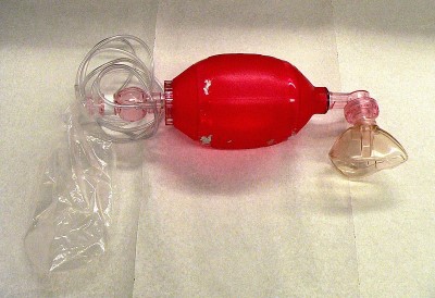
The bag valve mask (also known as Ambu bag or manual resuscitator) model is a generic representation of a hand-held device commonly used to provide positive pressure ventilation to patients who are not breathing or not breathing adequately.
System Design
Data Flow
Preprocess
The bag valve mask equipment object modifies circuit and substance values during the preprocess phase. It sets the connection to the respiratory system based on the airway mode, applies settings, calculates the instantaneous driving pressure value, and sets substance and aerosol values at the source.
Process
The current implementation has no specific circuit or transport process functionality for the bag valve mask. Bag valve mask processing is currently done in the Respiratory System with the combined circuit methodology.
Postprocess
The Postprocess step moves values calculated in the Process step from the next time step calculation to the current time step calculation. The current implementation has no specific post process functionality for the bag valve mask. All postprocessing is done in the Respiratory System with the combined circuit methodology.
Features and Capabilities
The Bag Valve Mask Circuit
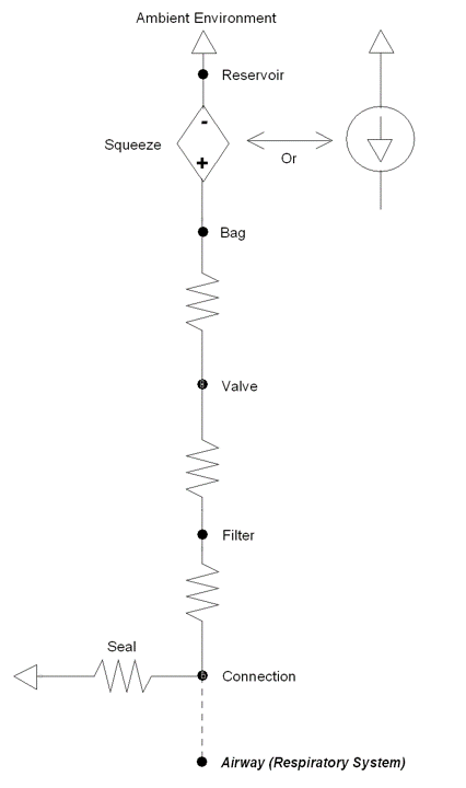
The bag valve mask model consists of a pressure/flow source to model bag squeezing. Resistances are present between the bag, valve, filter, and connection. There is a seal resistance that determines the amount of air that escapes during the simulation. Figure 2 shows the bag valve mask circuit. The compartments and transport graph mirrors the circuit. Substance values are set on the reservoir node/compartment, assuming infinite volume.
Connecting to the Respiratory Circuit
When the bag valve mask is used on a patient, there is a direct connection that allows air to flow freely between both. In the same fashion, the bag valve mask and Respiratory circuits in the engine are directly connected and allowed to share the same fluid. When in use, both individually defined circuits are combined into a single circuit that is then used for calculations.
Bag Valve Mask Settings
The bag valve mask can be applied in combination with the intubation action with a mask, oropharyngeal, or nasopharyngeal connection. The model includes the following configuration options:
- Connection: On, Off
- Valve Positive End Expired Pressure: PEEP valve setting for minimum pressure during exhalation
- Fraction Inspired Gases: Sets bag gases, including fraction of inspired oxygen (FiO2)
- Concentration Inspired Aerosols: Sets bag aerosol concentrations, including aerosolized drugs
- Circuit Resistances
- Bag Resistance: Total resistance of the bag connection
- Filter Resistance: Total resistance of the filter
- Valve Resistance: Total resistance of the valve
- Seal Resistance: Total resistance of the leak
- Circuit Volumes
- Filter Volume: Total volume of air in the filter
- Connection Volume: Total volume of air in the mask/tube
- Valve Volume: Total volume of air in the valve
Bag Valve Mask Actions
The bag valve mask can be driven in three different ways with different parameters as outlined below:
Instantaneous mode: Applies a specific pressure or flow value at the bag until overriden or removed by the user
- Squeeze pressure or flow
Squeeze: Perform one full squeeze cycle
- Squeeze pressure or volume
- Expiratory period
- Inspiratory period
Automated: Continuous application of squeeze cycles until stopped by the user
- Squeeze pressure or volume
- Breath frequency
- Inspiratory-expiratory ratio
Dependencies
The bag valve mask interacts with the Respiratory System through a connection that delivers gases and aerosols into the Respiratory System (see Respiratory Methodology). The two systems are connected to each other through a path that connects the airway node of the Respiratory System to the mask node (referred as Connection in the circuit diagram) of the bag valve mask. During spontaneous ventilation, the airway node of the Respiratory System is connected to the atmosphere via the Environment System. This serves as a ground node for the Respiratory System.
When the bag valve mask is connected, a network of combined circuits that include the elements from both the Respiratory and bag valve mask systems is created. When the combined circuit is generated at runtime, the ground environment node connected to the mouth node of the Respiratory System is replaced by the Connection node that represents the mask node, becoming one combined circuit. Apart from such interaction, the bag valve mask is also responsive to the flow resistances of the Respiratory System. In this regard, the bag valve mask driver pressure serves as a positive-pressure source for the combined circuit. The bag valve mask is linked to the Environment System that regulates the atmospheric/reference pressure.
Assumptions and Limitations
Currently, the bag valve mask uses ideal pressure/flow sources.
Results and Conclusions
Validation
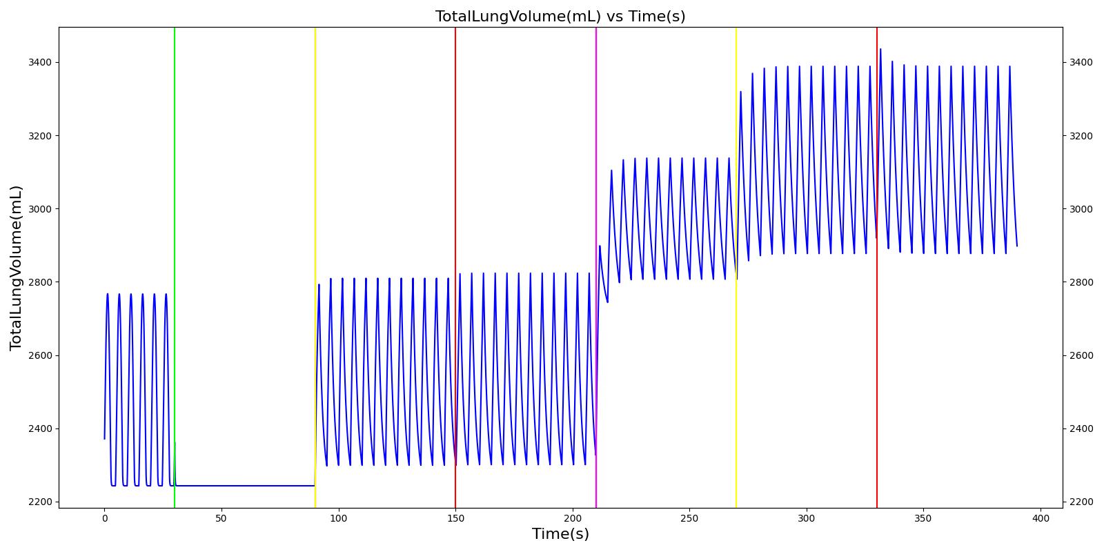
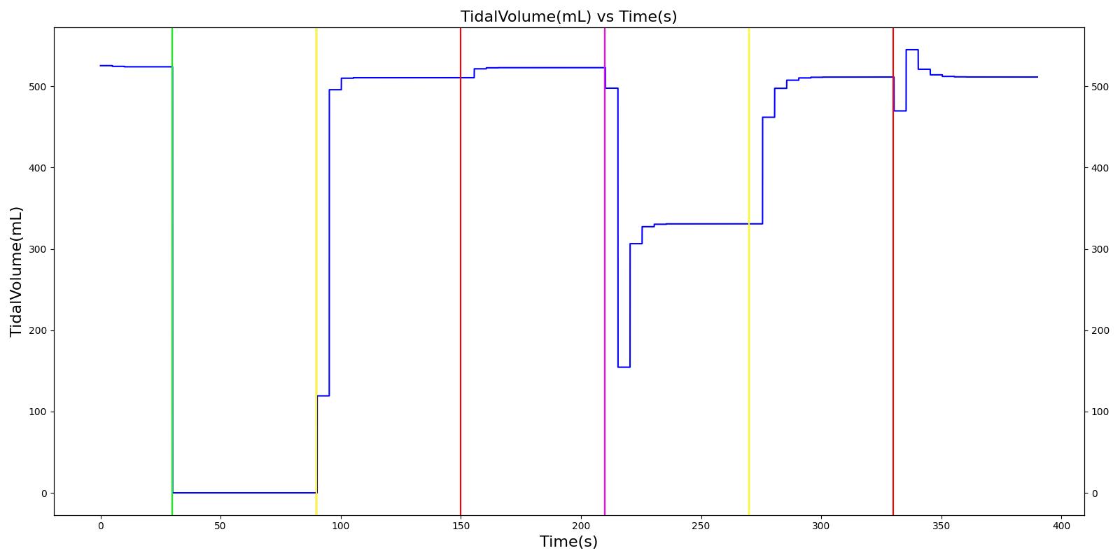
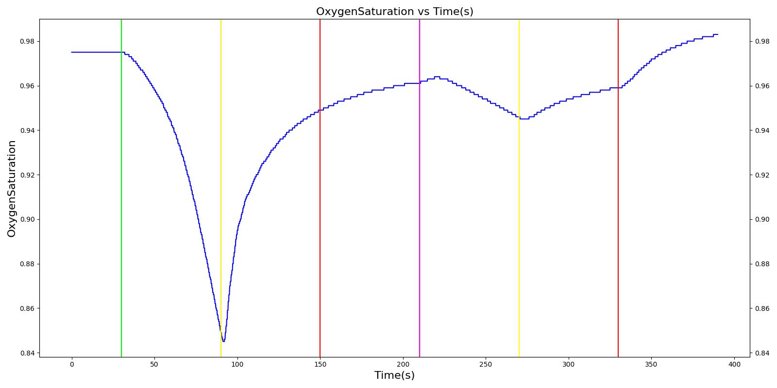
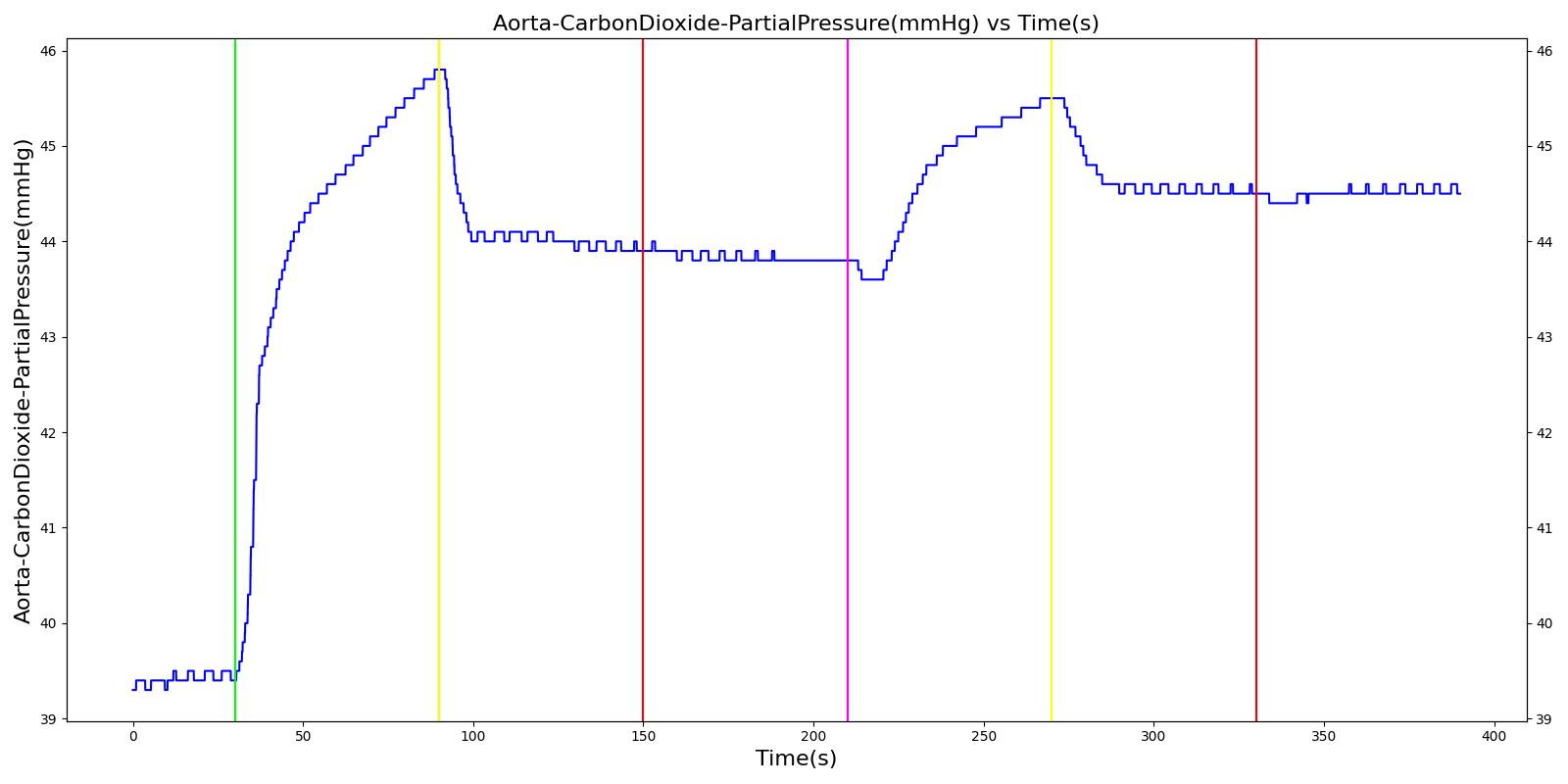
The bag valve mask settings are fully dynamic. A scenario that varies the settings in several different combinations on a apneic patient is included with the code base and produces the outputs shown in Figure 3.
 |  |
 |  |
 | |
Table 1. Validation results for the bag valve mask scenario.
| Key |
|---|
| Good agreement: correct trends or <10% deviation from expected |
| Some deviation: correct trend and/or <30% deviation from expected |
| Poor agreement: incorrect trends or >30% deviation from expected |
| Segment | Action Occurrence Time (s) | Sampled Time (s) | Respiration Rate (bpm) | Tidal Volume (mL) | Inspiratory-Expiratory Ratio | Oxygen Saturation | Arterial Carbon Dioxide Pressure (mmHg) |
|---|---|---|---|---|---|---|---|
| Dyspnea: severity = 1.0 (apnea) | 30 | 90 | 0 (apnea) | 0 (apnea) | 0 (apnea) | Decrease | Increase |
| Oropharyngeal intubation; Automated BVM: Comment: Automate a squeeze pressure to give TV ~ 7 mL/kg(ideal), BreathFrequency: 12(1/min), InspiratoryExpiratoryRatio: 0.5, SqueezePressure: 9.3(cmH2O), SqueezeVolume: NaN | 90 | 150 | 12 (setting) | 540 (setting) | 0.5 (setting) | Increase | Decrease |
| Remove SqueezePressure and apply SqueezeVolume: 0.54(L) | 150 | 210 | 12 (setting) | 540 (setting) | 0.5 (setting) | No change | No change |
| Remove intubation and attach mask; PEEP: 5(cmH2O) BreathFrequency: 12(1/min), InspiratoryExpiratoryRatio: 0.5, SqueezePressure: 12.3(cmH2O), SqueezeVolume: NaN | 210 | 12 (setting) | Decrease | 0.5 (setting) | Decrease | Increase | |
| Remove SqueezePressure and apply SqueezeVolume: 0.54(L) | 270 | 330 | 12 (setting) | 540 (setting) | 0.5 (setting) | Increase | Decrease |
| Attach oxygen to the reservoir with FiO2 = 0.3 | 330 | 390 | 12 (setting) | 540 (setting) | 0.5 (setting) | Increase | No change |
Conclusion
While the model is a generic representation of the application of a bag valve mask, inhaled gases, and inhaled agent administration, this model represents the behavior of a complex piece of equipment that is associated with a difficult medical specialty. The engine provides a whole-body approach to modeling that allows for simulation of this complex field. This system is a strong addition to the engine.
Future Work
Coming Soon
Nothing is currently planned.
Recommended Improvements
The bag could be modeled as a compliance to be closer to reality.
Appendices
Data Model Implementation
Acronyms
FiO2 - Fraction of Inpspired Oxygen
PEEP - Positive End Expired Pressure
SpO2 - Oxygen Saturation
Compartments
- Reservoir
- Bag
- Valve
- Filter
- Connection